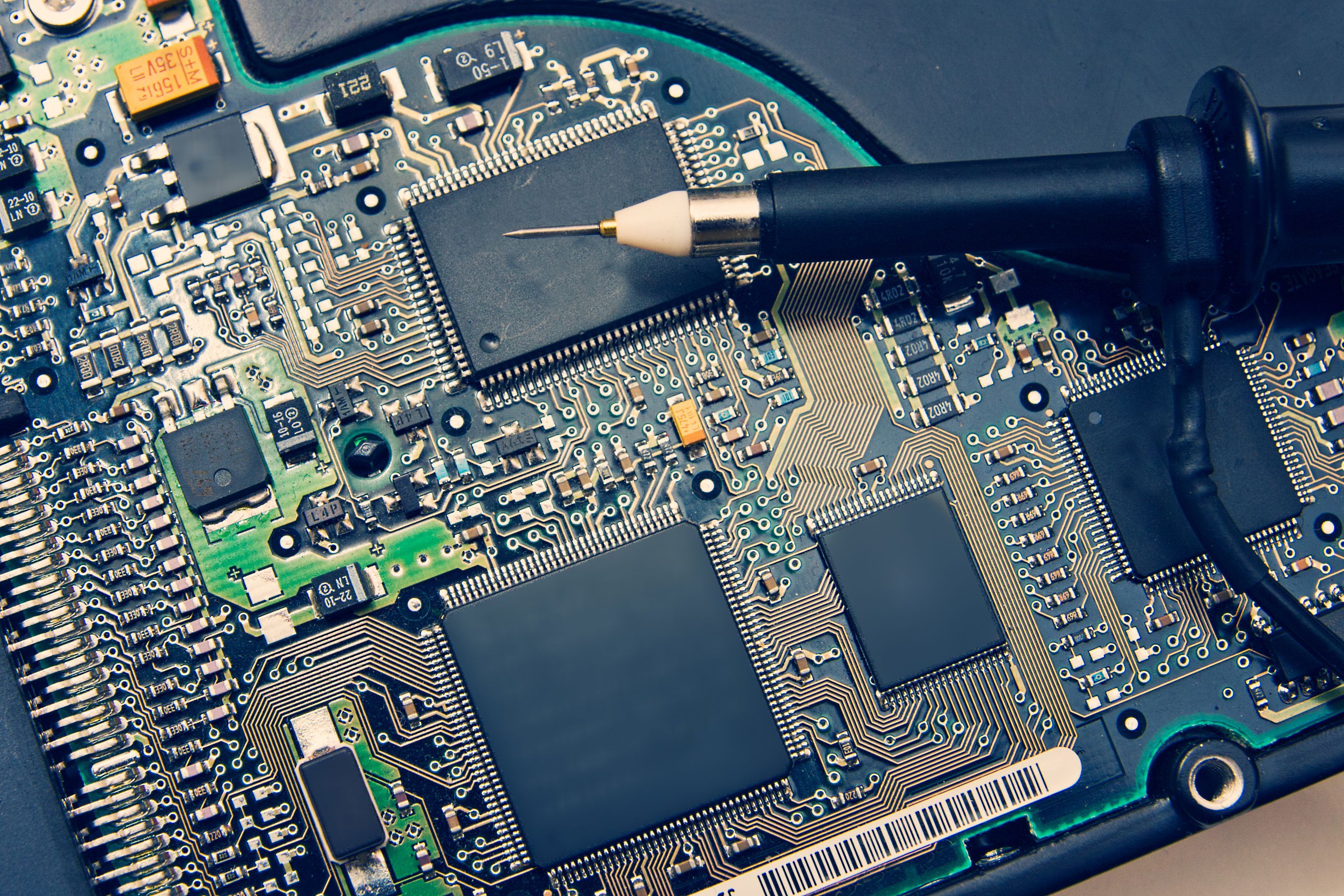
An oscilloscope is an essential tool for anyone involved in PCB troubleshooting or PCB repair. While multimeters can check DC voltages and continuity, they miss dynamic signal behavior. An oscilloscope visualizes voltage over time, revealing issues like noise, timing problems, signal integrity failures, and intermittent faults that are invisible otherwise.
Common PCB problems include:
- Power supply instability (ripple, dropout)
- Missing or distorted clock signals
- Communication bus errors (UART, SPI, I2C)
- Analog circuit malfunctions (amplifiers, filters)
This guide walks through practical steps to use an oscilloscope for effective PCB troubleshooting.
Preparation Before PCB Troubleshooting
Required Tools:
- Oscilloscope (at least 100MHz bandwidth recommended for modern PCBs)
- Passive probes (1x/10x, with good grounding)
- Multimeter (for initial DC checks)
- Soldering iron, flux, and basic hand tools
- Optional: Logic analyzer for digital buses, current probe for power
Safety Precautions:
- Power off and discharge capacitors before probing.
- Use isolated probes or differential probing for high-voltage sections.
- Avoid shorting adjacent pins—use fine-tip probes or spring grounds.
- Work in an ESD-safe environment.
Basic Oscilloscope Setup:
- Connect probes (use 10x for most digital/analog work to reduce loading).
- Set coupling to DC (AC for ripple measurements).
- Adjust vertical scale (e.g., 1V/div or 500mV/div) and time base (start wide, zoom in).
- Enable auto-setup or trigger on edge for quick signal capture.
Step-by-Step PCB Troubleshooting with Oscilloscope
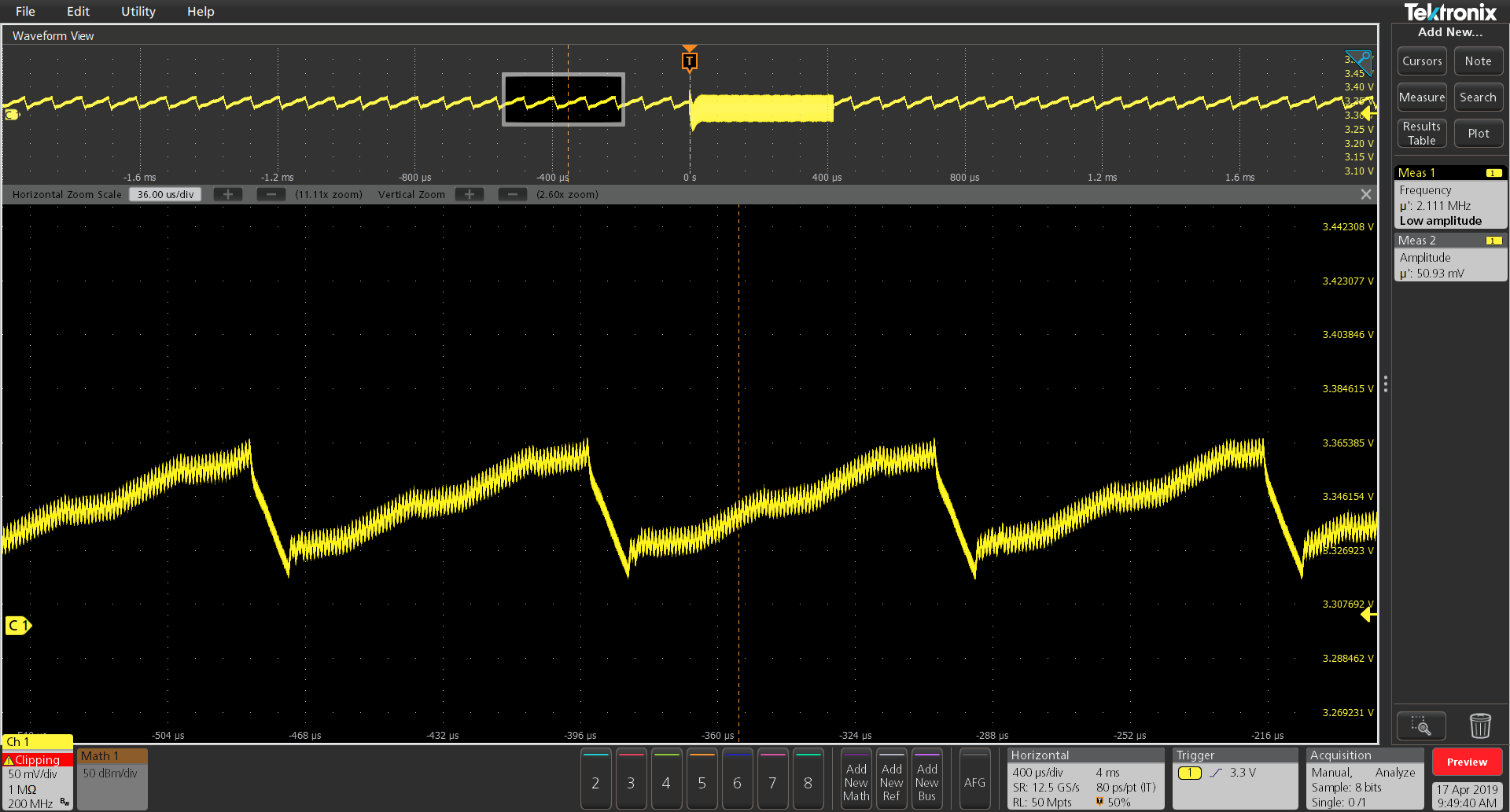
Step 1: Check Power Supply Signals
Power issues cause ~70% of PCB failures. Measure DC voltage first with a multimeter, then use the oscilloscope to inspect ripple and noise.
- Probe across power rails (VCC to GND) with AC coupling and high sensitivity (e.g., 20mV/div).
- Look for excessive ripple (>50-100mV often problematic), switching noise, or transients.
- Use math functions or built-in ripple measurement if available.
Step 2: Check Clock Signals
Clocks are the heartbeat of digital circuits. Faulty clocks prevent MCU/FPGA operation.
- Probe crystal oscillator output or clock pins.
- Expect clean square waves with fast rise/fall times.
- Check frequency, amplitude, duty cycle, and jitter.
- Look for ringing, overshoot, or missing pulses.
Step 3: Check Data Communication Signals
Digital interfaces like UART, SPI, and I2C are common failure points.
- For UART: Probe TX/RX lines; check baud rate timing and clean edges.
- For SPI/I2C: Probe CLK and DATA lines together (use two channels).
- Verify start/stop conditions, clock stretching, ACK/NACK, and signal levels.
- Look for slow rise times (due to capacitance) or crosstalk.
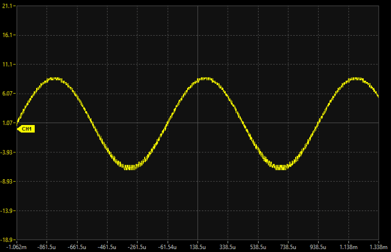
Step 4: Check Analog Signals
Analog sections require precise waveform inspection.
- Probe input/output of op-amps, filters, or sensors.
- Compare expected vs. actual signals (sine, ramp, etc.).
- Check for clipping, offset errors, noise, or distortion.
Common PCB Fault Cases
-
Power Noise: Excessive ripple from bad caps or poor layout—replace electrolytic capacitors.
-
Clock Failure: No oscillation (dead crystal) or weak signal—check load caps or replace oscillator.
-
Signal Distortion: Ringing from impedance mismatch or slow edges—add termination resistors or improve PCB routing.
Recommended Oscilloscopes for PCB Debugging
For hobbyists and professionals doing PCB repair, consider these reliable options:
-
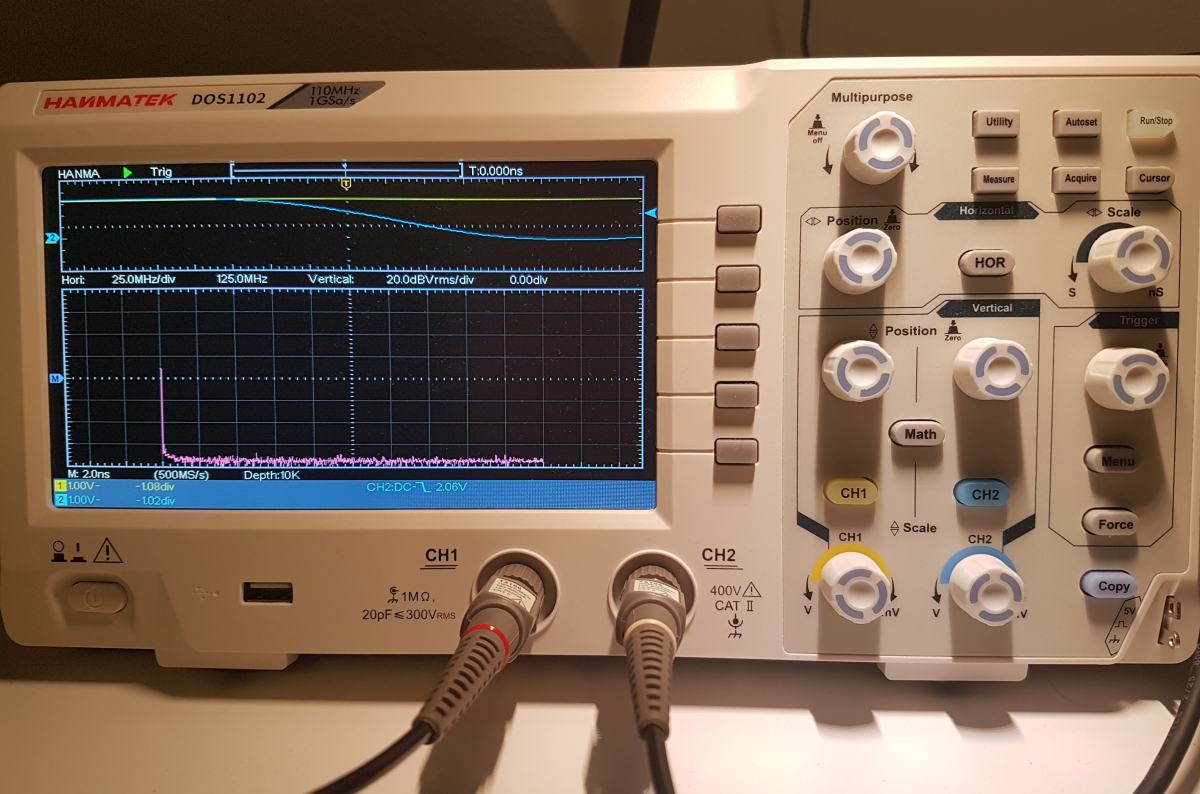
Hanmatek DOS1102 — 110MHz, 2-channel, affordable with solid performance for most digital/analog work. Check it out here
-
Hanmatek DOS1104 — 110MHz, 4-channel for complex multi-signal debugging (great for buses). Check it out here
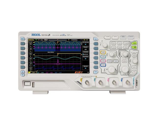
-
Rigol DS1054Z — Popular 50MHz (hackable to 100MHz), 4-channel with excellent features for the price.
Summary
Mastering oscilloscope PCB troubleshooting comes down to systematic probing: start with power, then clocks, communication, and analog paths. Use proper grounding, appropriate probe settings, and zoom in on anomalies.
Tips for Beginners:
- Practice on known-good boards.
- Learn trigger modes (edge, pulse).
- Save waveforms for comparison.
- Combine with schematics and datasheets.
With practice and a capable oscilloscope like the Hanmatek models, you'll diagnose and repair PCBs faster and more confidently. Happy troubleshooting!


Leave a comment