
Free Returns Guarantee
Free & Easy Returns
Free & Easy Returns

When comparing oscilloscopes, one specification that often confoses beginners is sample rate. You may see figures such as 100 MS/s, 500 MS/s, or 1 GS/s, but what do they actually mean—and why do they matter in real-world debugging?
Understanding sample rate is essential for accurate waveform analysis. Even a high-bandwidth oscilloscope can produce misleading results if its sampling rate is insufficient.
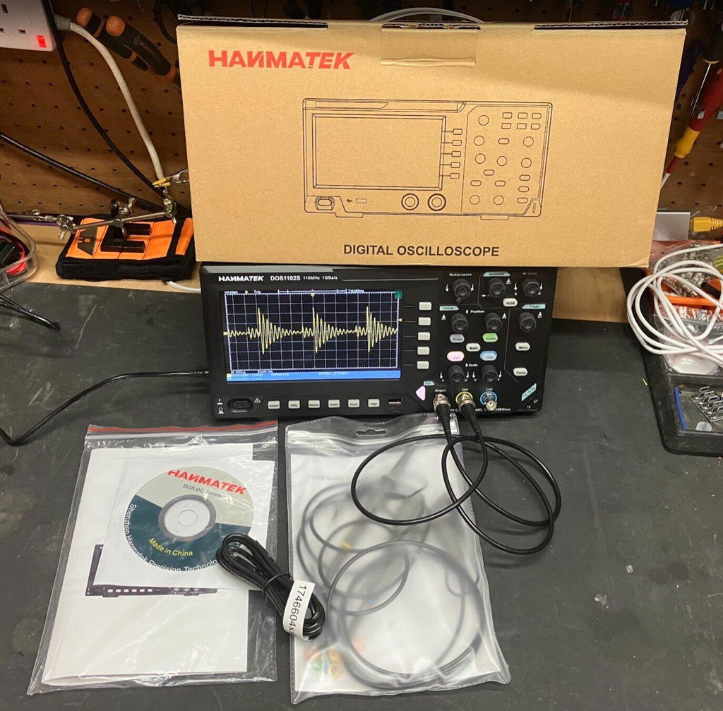
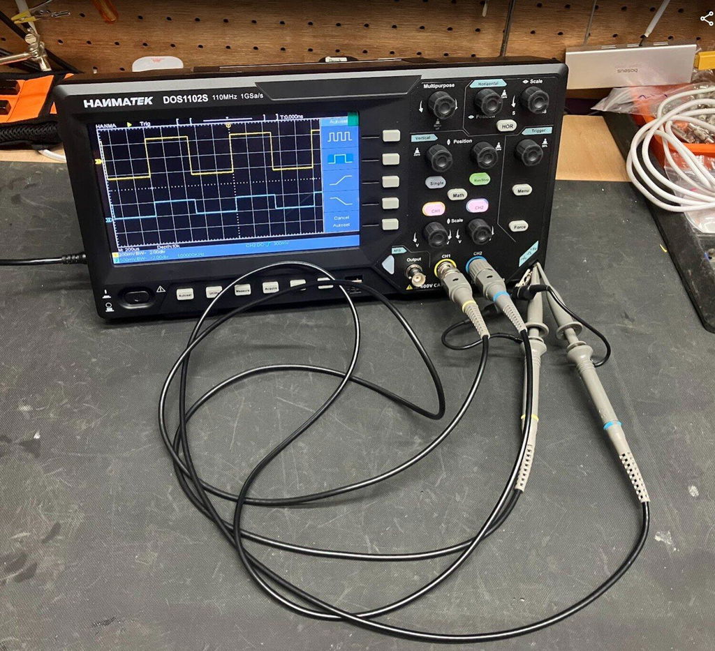
This guide explains how oscilloscope sample rate affects measurement accuracy, how it relates to bandwidth, and why a 1 GS/s oscilloscope is well suited to most electronics development, embedded systems, repair, and educational applications. We'll also introduce the HANMATEK DOS1104, a 4-channel benchtop oscilloscope that combines 110 MHz bandwidth with 1 GS/s real-time sampling.
According to the Test & Measurement Market Analysis published by Fortune Business Insights, increasing demand for embedded electronics, industrial automation, EV development, and intelligent manufacturing continues to drive adoption of higher-performance digital oscilloscopes. As electronic systems become more complex, engineers increasingly prioritize both bandwidth and sampling rate to ensure reliable signal analysis.
Manufacturer Quality Note: HANMATEK states that its oscilloscopes are manufactured under established quality management processes. If applicable, you may also mention official certifications (such as ISO 9001) only if independently verified.
Sample rate describes how many times per second an oscilloscope samples an incoming signal.
It is commonly expressed as:
For example:
The more samples collected, the more accurately the oscilloscope reconstructs the original waveform.
Conclusion
A higher oscilloscope sample rate improves waveform reconstruction accuracy and increases the likelihood of capturing fast transient events that lower-speed instruments may miss.
Supporting Data / Example
A 1 GS/s oscilloscope records one billion samples per second, providing approximately 9 samples per cycle when measuring a 110 MHz signal. This sampling density enables significantly better edge definition and timing analysis than lower sampling rates, particularly when debugging high-speed digital interfaces or switching circuits.
Unlike analog instruments, digital oscilloscopes reconstruct signals from discrete sample points.
If the sampling rate is too low:
With a higher sample rate:
These advantages are particularly important in embedded electronics and digital communication.
Although often confused, bandwidth and sample rate measure different aspects of oscilloscope performance.
| Specification | Primary Function |
|---|---|
| Bandwidth | Maximum signal frequency accurately displayed |
| Sample Rate | Resolution and detail of waveform reconstruction |
A commonly accepted engineering guideline is to choose a sampling rate at least 5–10× higher than the highest frequency component of interest, helping minimize aliasing and improve waveform fidelity.
Conclusion
Oscilloscope bandwidth determines the frequency range that can be measured, while sample rate determines how accurately the waveform is reconstructed.
Supporting Data / Example
For a 110 MHz oscilloscope, a 1 GS/s sampling rate provides roughly a 9:1 sampling ratio, aligning with widely accepted engineering recommendations of using sampling rates 5–10 times higher than the signal frequency for reliable waveform analysis.
A 1 GS/s oscilloscope captures one billion samples every second, offering enough temporal resolution for a broad range of engineering tasks.
1 GS/s Oscilloscope Applications include:
Higher sampling density makes signal edges clearer and timing relationships easier to evaluate.
Short-duration events such as:
may be missed by lower-speed oscilloscopes. A higher sampling rate significantly improves the probability of capturing these transient faults.
Higher sample rates improve:
Conclusion
A 1 GS/s oscilloscope provides sufficient sampling performance for the majority of embedded system debugging tasks encountered in education, product development, and electronics repair.
Supporting Data / Example
During an ESP32 debugging session, engineers may simultaneously observe a 40 MHz SPI clock, UART communication, PWM outputs, and power rails. Combined with four independent input channels, a 1 GS/s oscilloscope enables synchronized observation of timing relationships that would otherwise require multiple measurement sessions.
Consider debugging an ESP32 development board.
Typical signals include:
With insufficient sampling:
At 1 GS/s, these signals can be observed with substantially greater clarity.
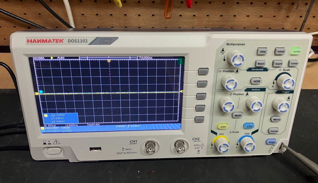
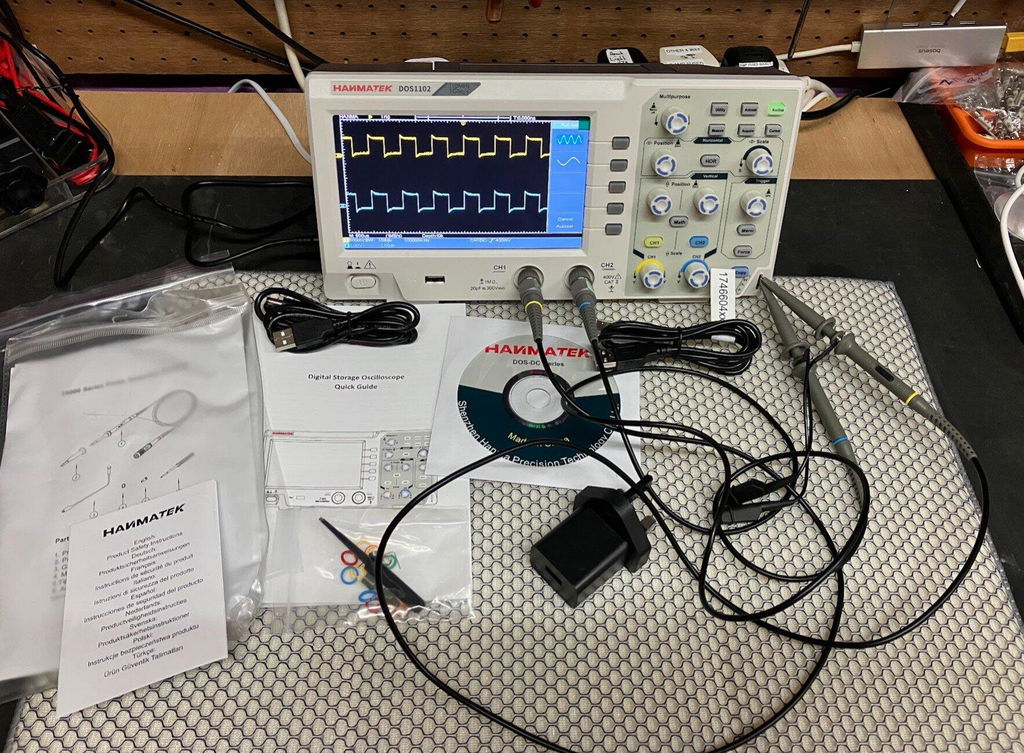
For engineers, repair technicians, educators, and makers seeking balanced performance and value, the HANMATEK DOS1104 combines practical specifications for everyday electronics work.
Product Page
| Feature | Specification |
|---|---|
| Bandwidth | 110 MHz |
| Sample Rate | 1 GS/s |
| Channels | 4 |
| Display | High-resolution Color LCD |
| Applications | Embedded Systems, Electronics Repair, Industrial Control, Education |
The combination of:
supports many common applications, including:
HANMATEK also provides an oscilloscope tutorial covering setup, triggering, and measurement techniques.
📖 https://hanmatek.com/es/pages/benchtop-oscilloscope-tutorial
Although bandwidth often receives the most attention, sampling rate is equally important for accurate waveform analysis.
A 1 GS/s oscilloscope offers practical performance for most electronics applications by providing:
Combined with 110 MHz bandwidth and four input channels, the HANMATEK DOS1104 delivers a balanced solution for embedded development, electronics repair, industrial troubleshooting, and engineering education.
{"one"=>"Select 2 or 3 items to compare", "other"=>"{{ count }} of 3 items selected"}



Leave a comment